Construction of the Royal Crescent
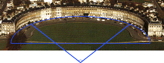
- The Royal Crescent
Construction diagram for the semi-ellipse of the Royal Crescent: the two small arcs at both ends have their centres on the top two angles of the equilateral triangle, the large arc in the middle has its centre on the lower angle.
Explanation (Animation)
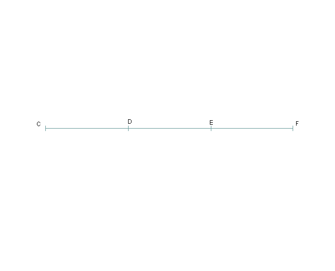
The Royal Crescent is a semi-ellipse with a major axis of 540 ft.
John Wood first mathematically plotted the design on paper: the drawing on his deed of conveyance shows three compass pricks.
He then transferred it on the ground with a theodolite. It is an example of the new geometrical approach to urban planning.
He first placed three control points on the base line so that CD=DE=FG=180 ft.
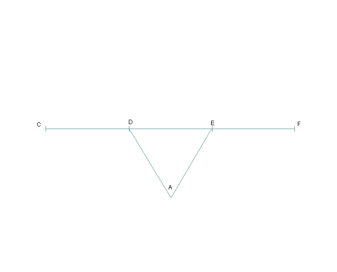
He next placed a control point A so that ADE formed an equilateral triangle.
His papers specify that he should be allowed to “set up a stone pillar” (at A) and “resort there to take views for the better forming the building”
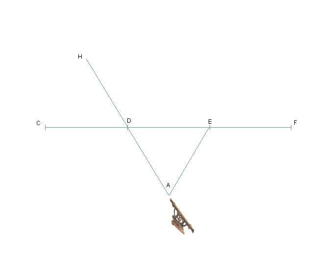
Wood set up the theodolite (not to scale in this diagram) on the pillar and looked through it through points D and E to mark out two points H and J.
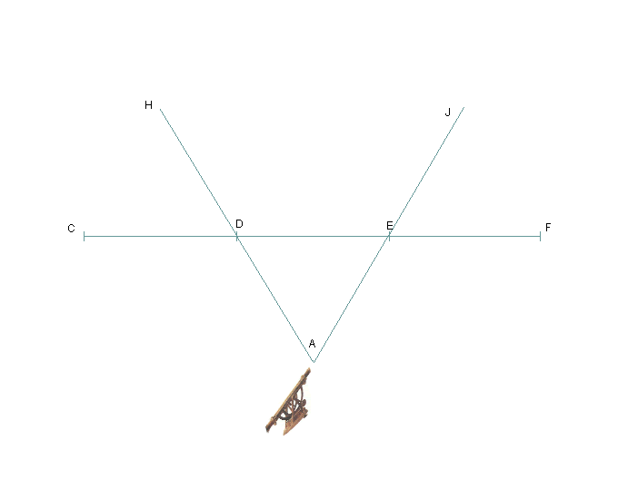
Wood set up the theodolite (not to scale in this diagram) on the pillar and looked through it through points D and E to mark out two points H and J.
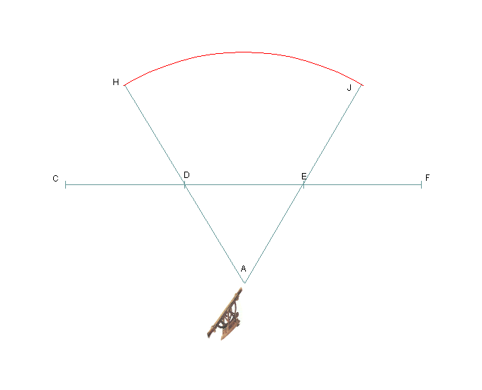
Wood would then sight through the theodolite at a workman at a workman holding up a stick.
The middle arc would be pegged out.
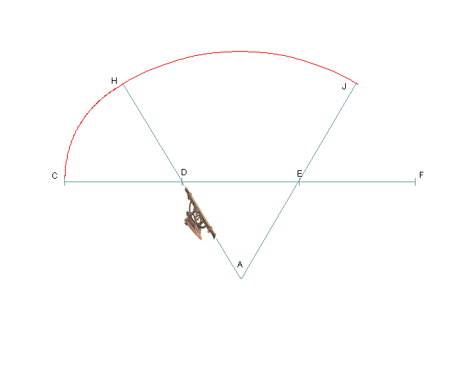
Wood would then move the instruments to D and E to mark out the two curves CH and JF.
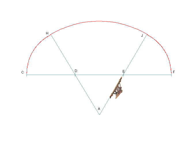
Wood would then move the instruments to D and E to mark out the two curves CH and JF.
After a design and comment by John Mullen, The Museum of the Building of Bath, 1992)
Bath Preservation Trust

